[Introduction]
[Requirements]
[Hardware and camera]
[Installing software]
[Configuration]
[Program output]
[Logging]
[Error reporting and support]
Introduction
dialEye is an application for reading the rotating dials of a utility meter
(water, gas, etc.). It uses image processing to determine the angles of
the rotating dial needles and combines the result to a counter value.
dialEye needs to be configured and clibrated so that it is aware where in the
meter image the dials are located and what are the 0-angles of the dial
needles. In addition special positioning areas can be configured to
deal with possible movement of the camera in relation to the meter.
The meter counter value represents the position the dial needles are at a
time. Periodically metering and comparing the counter value change, the
consumption value can be calculated.
This howto is based on an example provided with the dialEye application
package (sample dialEye.conf configuration file and sample
calibration image docs/dialeye_calibration.jpg).
Requirements
Requirements for running the application are:
Hardware and camera
dialEye is not dependent on certain image size, camera type or image format.
However there are some rules that should be taken into account when planning
the camera setup. You might use a network capable camera or a $0.99 web
camera from Hong Kong (I have done both with success, though the cheap webcam
one did stop working after year of successful operation). As you see from the
example images below, the picture does not have to be crystal sharp. There is
one key driving element though:
You should try to keep the setup and environment constant.
Some tips to consider when planning your setup:
- Mount the camera so that it is more likely that the meter will stay
in the same position in the camera image and that no-one kicks or moves the
camera.
- Keep the light conditions as constant as possible. I use external
white LED light to light the meter.
- Detection algorithm works better with full color picture. Do not use
IR-light because it flattens the colors and "discards" color information
making it harder to detect the dials.
- When you light the meter, be sure there are no reflections on the meter
glass on top of the dials that are being detected. Light reflections are
OK in areas outside the dial circles.
- If sunlight/outside light reaches your meter, consider covering the setup
to make things constant.
dialEye is able to get the image from network camera using HTTP (Basic auth
is supported) or from an image file on the file system.
Example photos of existing camera setups:
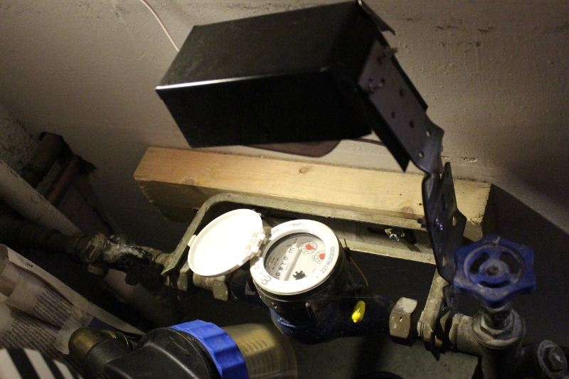
- Installation 1:
D-Link network camera (WLAN) mounted to the meter stand with all
the construction iron I could find... and covered with sheet metal
to protect from condence water dripping from above equipment.
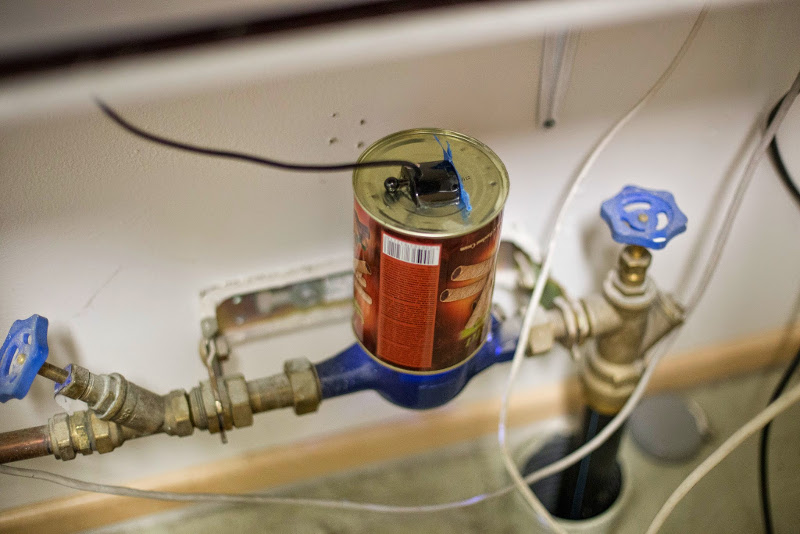
- Installation 2:
Cheap webcam mounted over the meter using a cookie can. Cam LEDs
have been changed from IR to white light. Cookie can protects from
sunlight.
Installing software
dialEye is simply installed by unpacking the distribution package to suitable
location in the target system directory tree.
Configuration
The basic dial and needle value detection requires information about where in
the meter image the dials are located, how big is the dial area and what is the
geometry of the needle. Also detection treshold value can be adjusted.
In addition the application can be configured to first search known parts of
the supposed image to properly locate the dials should the positioning of the
meter and camera have shifted slightly from some reason.
dialEye package comes with an example configuration file
dialEye.conf that matches the example calibration image found
in the docs folder. The following prodcedure explains how
the sample configuration has been done and meaning of each value.
The exmaple configuration file also includes comment rows
(beginning with #-mark) that further document possible
configuration parameters and their possible values.
Calibration image
First thing to configure is to obtain a calibration image from your meter
and camera combination. Use an image that is taken with your installed
setup, camera position and light conditions. Below is the calibration image
on this example - the starting point of my configuration.
The calibration image is configured in the configuration file with key
CALIBRATION_IMAGE:
CALIBRATION_IMAGE = docs/dialeye_calibration.jpg
Dials
Configuration first lists the dials on the calibration image with
@DIAL configuration keys. The image may contain from 1 to
unlimited amount of dials. The dial configuration lists dials in
significance order. The most significant dial must be configured as
topmost in the configuration file. The dials will be processed in the
order they are listed and will produce the output value digits in
that order.
The syntax of the @DIAL-row is:
@DIAL=center_x:center_y:meter_radius:inner_radius:needle_angle:needle_angle2:zero_angle:rot_dir[:needle_color]
Where:
center_x |
Horizontal pixel coordinate of the center of the dial (0 is in left)
|
center_y |
Vertical pixel coordinate of the center of the dial (0 is in top)
|
meter_radius |
Dial metering circle radius in pixels. Outer area of the meter.
|
inner_radius |
Dial metering inner circle radius. Affects the speed of the metering algorithm.
|
needle_angle |
Width of the needle in degrees on the outer circle.
|
needle_angle2 |
Width of the needle in degrees on the inner circle.
|
zero_angle |
Angle of the dial zero value compared to the picture
vertical axis. Straight up would be 0.0 degrees, pointing
to the right would be 90.0. Value must be between 0 and
360 degrees.
|
rot_dir |
Direction of rotation. 0 for clockwise, 1 for counter clockwise.
|
needle_color |
(OPTIONAL) Color of the needle as RGB color integer triplet,
separated by ':'. Syntax: :red:green:blue
|
Example @DIAL-row (without needle color):
@DIAL = 402:253:33:16:-1.0:50.0:3.5:0
Example @DIAL-row (with needle color):
@DIAL = 402:253:33:16:-1.0:50.0:3.5:0:152:57:65
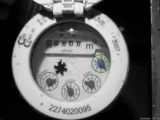
Let's start with most significant dial and by guessing the center point
of it (center_x, center_y) upper left corner being the (0,0) point.
Then set the meter_radius for example to 20 and left of the values to zero:
@DIAL = 350:250:20:0:0:0:0:0
dialEye can be asked to visualize the configuration on top of the calibration
image. The visualized configuration is stored to a image file
dialeye_conf.png or shown in a new window if -g
option is given and the system has graphical environment available
(Windows environment or X). The commands used to view the configuration:
python dialEye.py showconf
python dialEye.py -g showconf
The outputted image (in file or screen) will show the meter outer diameter
with green and at this point a red thin needle ending in the configured center
point.
Correct the center point and dial outer diameter so that the circle is
exaclty in the middle of the dial and the circle area covers fully the area
where the needle rotates. An image editing application (eg. GIMP or Paint.NET)
may be helpful to find out the pixel locations in the image, but trial error
is also feasible way to proceed. After the values are correct, the
showconf output should look like this:
Next we turn the red hairline "needle" to the direction where the needle
is in the calibration image. This is done by altering the
zero_angle value (in degrees) so that the needle line points
exactly in the needle direction in the calibration image.
The value is angle in degrees compared to the picture
vertical axis. Straight up would be 0.0 degrees, pointing
to the right would be 90.0. Value must be between 0 and
360 degrees. The end result should look like this:
Next we adjust the inner_radius value to form a smaller
circle inside the meter circle so that it limits the area where the actual
needle arm part moves. The center of the dial will always contain the
needle center and is of little use determining the needle angle. To speed
up the detection algorithm we limit the centre part out from the detection.
After setting the inner circle radius the configuration should look like this.
The area where the detection is done is between the green outer circle and the
blue inner circle:

Next configure the needle arm geometry in the detection area. This is done
by altering two angle values: needle_angle and
needle_angle2. The first one tells how wide the needle body is
when it hits the outer cirle (measured as an angle when looking from
the image center point). A negative angle means the needle does not
reach the outer circle, but if lines drawn on the needle egdes would
continue, how wide angle would the intersection points on the outer
circle make (as a negative value). The second one tells how wide the
needle body is in degrees when it hits the inner circle (similarily
measured as an angle viewed from the dial center point). When the
setting is correct, the red needle edge lines on the calibration
image should follow the actual needle edges:

Next, now that the needle geometry is correct, we turn the
zero_angle value so that the green dial center line
goes exactly through the dial 0-value-point in the meter background.
The dial configuration in the example should now look like this and
produce the calibration image below.
@DIAL = 402:253:33:16:-1.0:50.0:3.5:0
Finally for this first dial, determine the direction of rotation with
the rot_dir value (0 for clockwise, 1 for counter clockwise).
The green arrowhead on the dial outer circle shows the selected direction
in the showconf image.
The needle detection algorithm by default uses the average color in the
dial center point configured to determine what is the color of the needle
being detected from the detection area. However, if the needle centers are
of different color as the needle arm or there is some other disturbance
in the image (eg. light relection) to prevent determining the color of the
needle from the center point, you may need to configure manually the
color of the needle. The dial configuration may have additional three optional
integer numbers to determine the RGB color value for the needle. In this
howto example and with the image setup described here, this is not necessary.
Use again your favourite image editing application (GIMP, Paint.NET, etc.)
and using the color picker tool on your calibration image find out the
RGB-values of the needle part being detected. For example for the dial
configured above, we could add the needle color (RGB = 152,57,65)
to the configuration and the resulting dial configuration would be like:
@DIAL = 402:253:33:16:-1.0:50.0:3.5:0:152:57:65
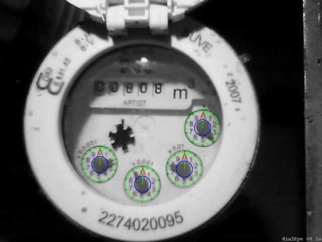
After setting the first and most significant dial, set up the remaining
in significance order using the process described above.
The dial configuration should look something like this when ready:
Positioning areas
Even the camera would be firmly attached to the meter body, there tends
to be small movement between the dials and the camera resulting the
detection areas moving slightly in the image. You can help dialEye
to deal with this by determining positioning areas in the calibration
image that can be used to locate the dials in the meter image.
The positioning areas are listed in the dialEye configuration file
using @POSAREA configuration keys.
The image may contain from 0 to unlimited amount of positioning areas.
However the recommendation is:
- use 3 areas that are clearly visible and spread in different
parts of the calibration image
- the positioning areas should not be located just beside the image
edge
- use fairly small areas. Large areas are more accurate, but
the image processing takes a lot more time when using large ones
- the positioning area boxes should be placed in areas having
some recognisable part of the image
- there should not be any changing or moving parts inside the
positioning area
The syntax of the @POSAREA-row is:
@POSAREA=x1:y1:x2:y2
Where:
x1 and y1 |
Pixel (x,y) coordinates of one corner point of the positioning area.
((0,0) is in the top left corner of the calibration image)
|
x2 and y2 |
Pixel (x,y) coordinates of the opposite corner point of the positioning area.
((0,0) is in the top left corner of the calibration image)
|
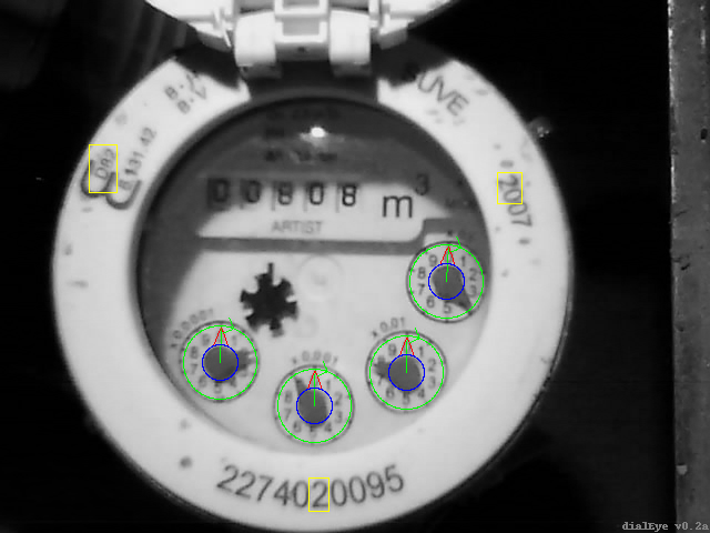
Configure the positioning areas again by trial error or using helpful
image tools. showconf visualizes the positioning areas as
yellow rectangles on the calibration image.
The sample positioning configuration looks like this and produces
the below configuration visualization:
    @POSAREA = 80:130:105:173
    @POSAREA = 448:155:470:183
    @POSAREA = 278:430:296:460
Image "shaking"
If at least one positioning area has been configured, dialEye
will by default try to "shake" the metered image (rotate the image and
move horisontally and vertically) to find a best match on the
positioning areas on the calibration image and the image being
detected/metered. The shaking process may be configured to look
farther in the image and/or rotate the image more. Larger area
and more travel when shaking will consume more time and processor cycles
when more positions and angle variations are calculated so
depending on your needs you may vary the parameters.
dialEye has been designed to be run periodically and therefore
it can save the "shake" result to a file after each detection. Because
of the saved state, the shaking parameters can be kept low so that the
time shaking consumes is mimimal and the movements are followed by the
process all the time because recent shaking results are saved. If however
the camera moves a lot quickly (for example it is accidentally bumped into
by someone), the shake parameters can be inreased to again find the sync.
The following configuration parameters affect the shaking process:
DISABLE_IMAGE_SHAKE |
By default dialEye uses the shake process before reading the dials, if
one or more positioning areas are defined. By setting this parameter to
true, you can disable the shaking process. (Default:
false) |
SHAKE_RADIUS |
The image may have moved horizontally or vertically.
This parameter configures the radius the image is moved to each
direction from the center point to find the best position relative
to the calibration picture positioning areas. Value 0
disables horisontal and vertical movement. Value 1 is
recommended for stable conditions (results to 9 different positions
being calculated). Use larger than 1 if you need more
processing to locate the dials. |
TURN_ANGLE |
The metered image is rotated by bottom center point of the image to
correct possible camera rotation. This parameter configures the maximum
amount in degrees the image is turned to both directions to find best match.
Values 1.0 or 0.5 are recommended for stable conditions.
|
TURN_ANGLE_STEP |
This parameters determines the stepping in degrees used in the rotation.
Smaller the steps and larger the angle, more angles are calculated and hence
longer will the turning take. Value 0.5 is recommended for stable conditions.
|
SHAKE_FILE |
This file is used to save the shaking result for next run. The shake
result is saved, if command line parameter -s is given with
the meter command.
(Default: dialeye_shakes.conf) |
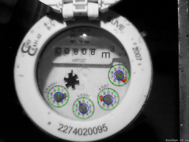
Needle detection
The configuration of the dialEye is almost ready. The needle detection
algorithm is controlled by two configuration parameters. The
parameter DETECTION_TRESHOLD controls the the
detection sensitiveness. Again configuring this value requires some
trial-error processing. We will try to detect the needles on the
clibration image. Detecting/metering is done with command meter
and the image begin processed will have to be given as a parameter
on the command line:
python dialEye.py -r meter docs/dialeye_calibration.jpg
The -r option tells dialEye to visualize the detection
over the metered image. dialEye generates dialeye_result.png
image visualizing the detection. Again adding -g option on
graphical environments will open the result image in new window.
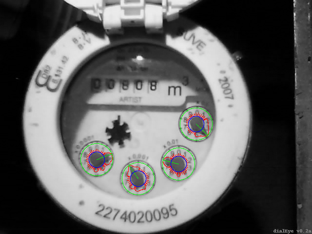
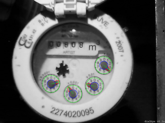
The visualization should be checked for two things: are the meter circles
located correctly where the dials are and are the needles detected
correctly. If the meter circles are not where they should be, the shaking
process has not been successful if the camera has moved. After the
dials are located correctly concentrate on the red needle detection tracks
and the detected green needle angle.
The DETECTION_TRESHOLD value (value between 0-100) can be
adjusted so that the needle detection is clear and the green dial angle lines
align just where the needles are in the metered image. Below are examples
of too small, too large and working treshold.
The DETECTION_TRESHOLD is too small. Some of the dial
needles are not detected and the detected ones look square (meaning that
the detection results are close to binary).
Increase DETECTION_TRESHOLD.
